Innovative Instrumentations for Landslide and Debris flow monitoring
Our instruments will be a new breakthrough which will boost the technology even further in landslide monitoring, prediction, management and policy decisions. A few key areas on the innovation front are interoperability, data models, Web services, and temporal and mobile Information System. Each of these areas will help hydrologist, water resources engineers with their work to provide a foundation for continued success.
Precision, Event-Trigger, Wireless and Lightning-free
SAKURA GSR helps to install Real-time Displacement Monitoring with Digital Wire Extensometer, Wireless Transmitter, weather monitoring sensors, digital camera and allied sensors with WiFi connections.
Several warning system and/or repeater station will be installed in a suitable location within the transmission distance to receive signals from multiple transmitters. Besides the signal of displacement, it can receive other signals of crack, groundwater, and soil saturation status, etc.
Thus the developed system will:
- Detect the signal of displacement based on the amount and rate to identify different levels of landslide event and provides an alarm signal.
- Provide the signal periodically so as to ensure stable operation and also indicate the power status.
Low power RF with transmission ranging up to 2km (with optional module) reduces the equipment and installation cost and power requirement. Extended cable up to a maximum of 400cm can reflect the landslide status.
Debris flow monitoring
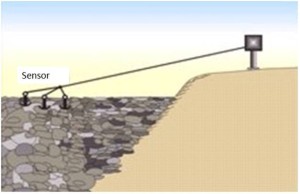
As shown in figure 1, Transmitter is set in the stream. It will monitor the displacement of anchors or big rock in the stream bed and will provide an alarm signal based on the amount and rate of displacement transmitted from the trigger pulse.
Figure 1 Debris flow monitoring concept
Landslide Monitoring
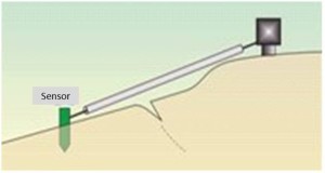
Transmitters are set in the upper and/or lower slope (Figure 2). It will monitor the potential and status of landslide, and will provide the signal per 1mm displacement and will trigger alarm according to the velocity change in the shallow ground.
Figure 2 Landslide monitoring illustration
Rock-fall Warning
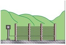
The transmitter is set on the Rock-Fall Catch Fencing (Figure 3). It provides the signal per 1mm displacement. According to the amount of the rock-fall, the station can warn the roadway users in time.

Figure 3 Rock fall warning system
Silt dam movement
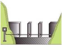
The transmitter is set in a slit dam or a debris dam (Figure 4). It provides the signal in the process of flow squeezing action and will trigger alarm based on the amount and rate of displacement transmitted from the trigger pulse. When the intensity of debris flow increases, it may make the cable broken or even departed from the snap.
Figure 4 Debris flow warning
Roadway slope Monitoring
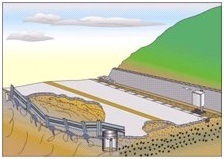
The transmitter is set in the roadway embankment (Figure 5). It monitors the potential and status at the ground surface across the head scarp of the lower slide and will provide the signal per 1mm displacement, and trigger alarm according to the velocity change. The cable can extend from one side of the failure zone to the other side through a flexible pipe buried in the trench.
Figure 5 Roadway slope monitoring
Settlement monitoring
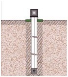
The transmitter is set on a ground surface. Anchors are mounted at the bottom of a borehole. The transmitter measures the amount of displacement between the anchors and the transducer base. It will also provide an alarm signal when the trigger pulse exceeds a preset level.
Figure 6 Ground surface displacement observation
Instrumentations
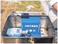
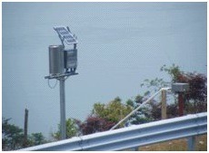
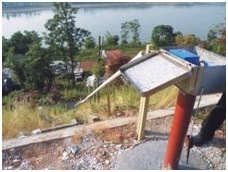
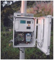
There appear geological disasters including collapse, slide, and debris flow. In addition to natural slopes, the excavated slopes referred to as cut slopes e.g. roadway slopes resulting from roadway excavations, which seriously result in a threat to public safety. In order to react to the considered phenomenon, the project will offer a series of cost effective products for displacement measurement and introduces the StormPanel to optimize the community-based early warning systems and provide other new solutions with Smart Repeater for durable and reliable environmental monitoring. Figure 7 shows combo images of proposed systems installed in some location of landslides prone-areas.
Figure 7 Sample images of the proposed systems
Automatic, Digital: The system adopts the auto-monitoring and event trigger method. Using RRS Digital Wire Extensometer for monitoring landslides ensures an evolutional up-grate to conventional analogue transducer. When the variations occur, the signal of per 1 mm displacement triggers the transmitter in pulse mode, at the same time; the digital data of highly precise position in absolute format can be read in serial mode. If no variations occur, transducer and transmitter consumes very low power and will be awakened by RTC and then transmit periodically to refresh the status.
Real-time, Trigger alarm, Wireless, Flexible: The Digital Extensometer detects events and triggers a transmitter which in turn sends instantaneous messages with RF signal for data acquisition and further alerts. The monitoring data are received and displayed on either StormPanel or SCADA systems. The transmitters are battery operated with a battery life of 2-5 years. With licensed free RF modules for wireless transmission, messages from multiple transmitters within an area can be received and/or repeated, the real-time monitoring and early warning for landslide or slope safety can be achieved.
Precise, Stable, False Alarm Prevention, Cost-effective: Advantages of such a method over conventional methods include the following: real time response to geo-deformation, precise displacement data; no need of filtering of cyclic fluctuations associated to daily cycle/year cycle and immunity to electromagnetic interference.
Through Digital Extensometer deployed at various locations, the displacement data derived from cable extension can be interpreted as various degrees of slope failure clearly.
Brochure (provide link)
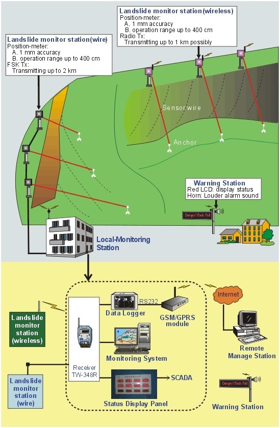
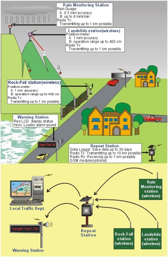
Schematic diagrams of the wireless and wired systems to be developed during this project are shown in Figure 8 and figure 9.
Wireless Field Monitoring Server for Advanced Sensors-network
Small monitoring robots called “Field Servers” which are equipped with a Web Server are shown in Figure 8. It utilizes Wireless LAN to provide a high-speed transmission network at low cost. By building a Web Server into sensor-network equipment, it is easy to access and manage by using a Web Browser such as Internet Explorer.
Generally conventional sensor network devices support only a few sensors and slow speed communication. They are insufficient for any applications such as model-base systems and do not meet the needs of users (Hydrologist, Agri, safety engineers). In the present system, the sensors communicate with the server at high speed, and acquire other relevant data such as air temperature, humidity, CO2 concentration and GPS for several applications. There is also a camera that provides high resolution images to monitor landslides sites (Figure 9).
The project will exploit a multifunctional outdoor server, Field Server (FS), which is compact, rugged and economical. In particular, FS is water-proof, dust-proof and heat-resistant. Field Monitoring Server (FMS) is FS for monitoring combined with a Web-server board, sensors, a wireless-LAN board and a special housing. To construct massively distributed monitoring system, that is a sensor-network using FMS, the system will use power saving technology. Regarding power supply, solar panel or battery will be expediently employed in remote FS in order to keep full wireless. These types of FS will have large solar panels for full-time working. Further, other type of FS will be equipped with smaller solar panels fixed on the top as shown in Figure 8 (b).
Figure 8 Schematic diagram of the sensors and networking
Figure 9 Monitoring systems along hilly routes

